Mixer Module Switch Wafers
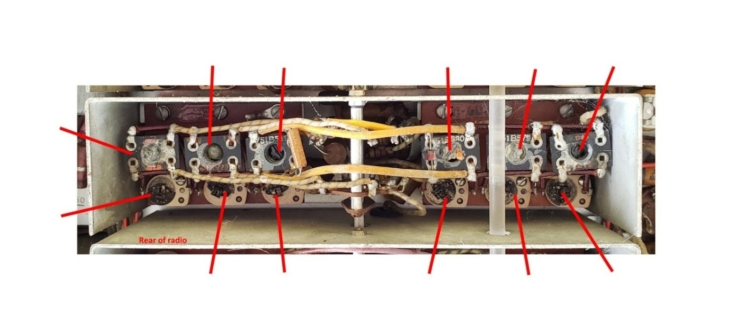
The mixer module has two wafers: 6 and 7 counting from the rear of the radio.
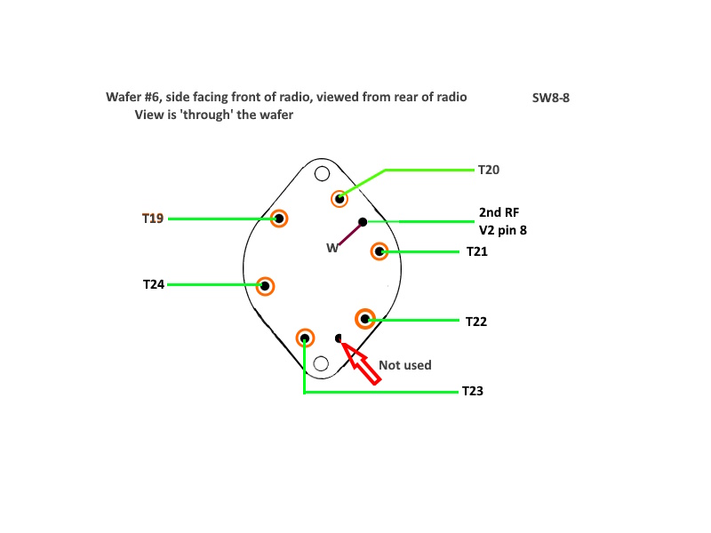
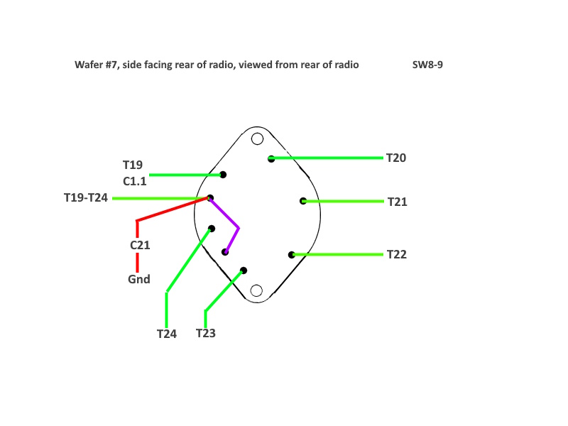
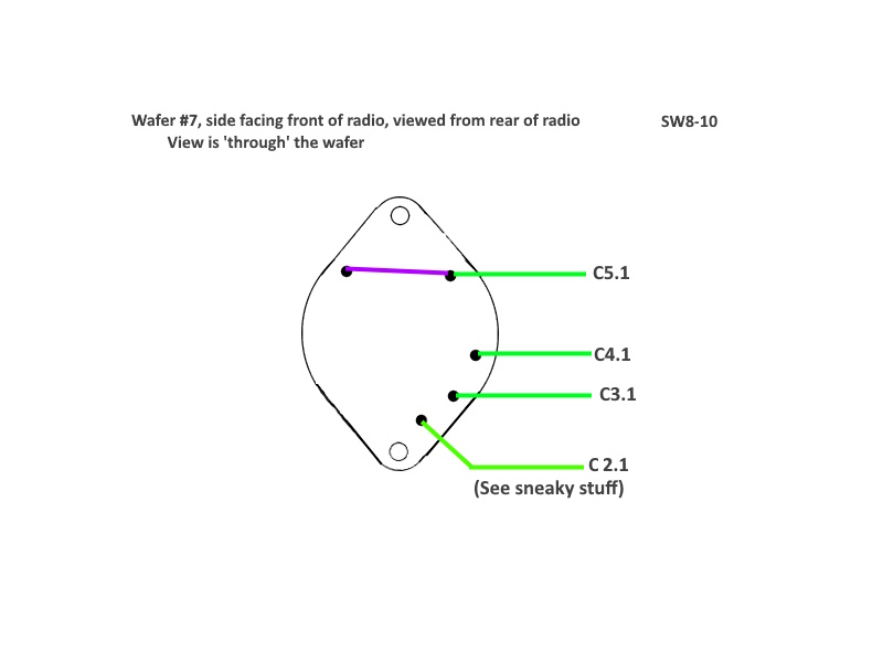
On the schematic, these switches are labeled SW8-8 and SW8-9/SW8-10 respectively.
This wafer distributes B+ (via R10 and C20) to the plate of the 2nd RF module through one of six transformer primaries.
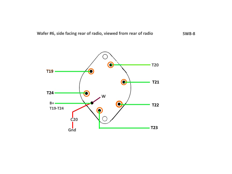
Beware of different viewpoints. One is 'through', the other is face on.
There is some seriously sneaky stuff going on in the mixer module.
This wafer selects one of six transformer secondaries and connects to the second grid of mixer tube V3.
This wafer selects which of the major tuning capacitors gets connected to the selected transformer secondary.
Beware of different viewpoints. One is 'through', the other is face on.
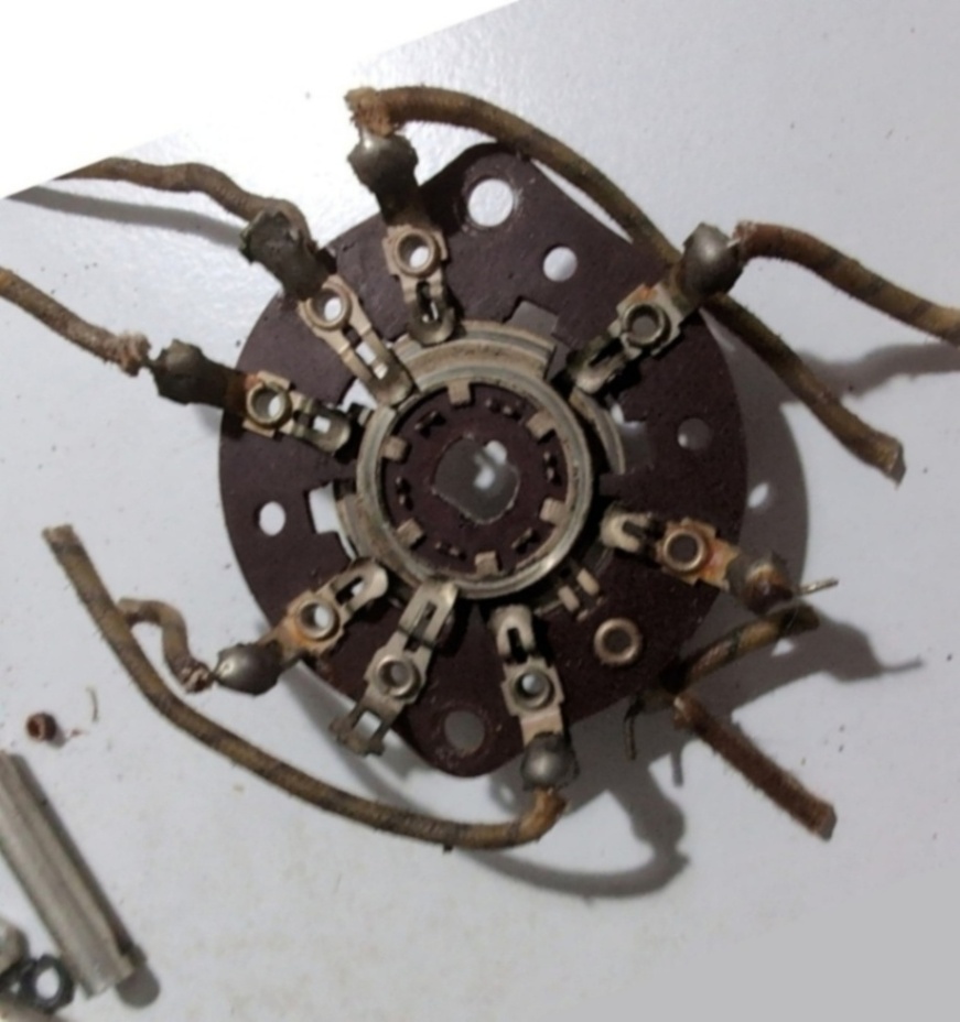
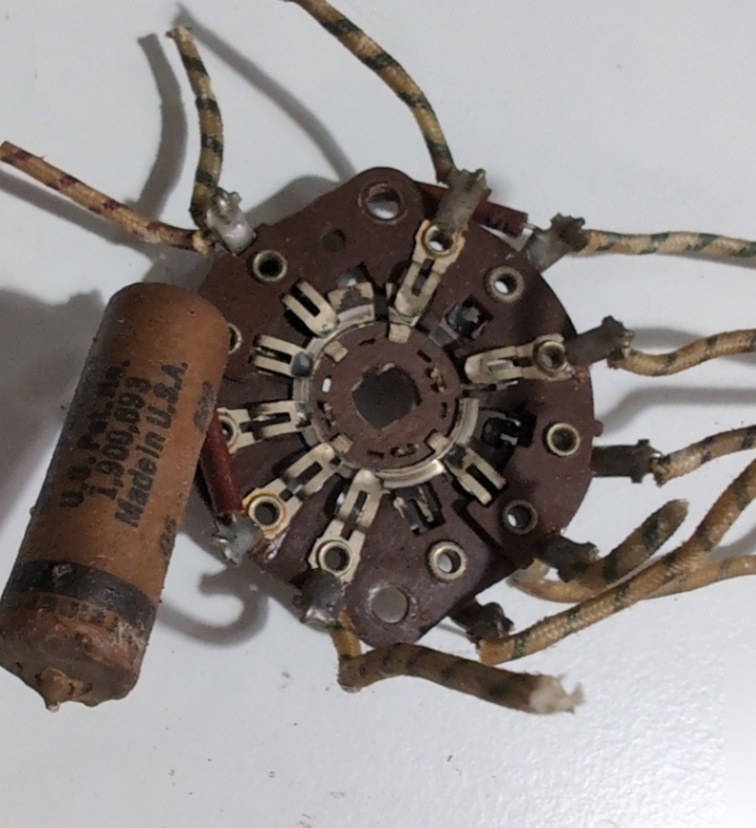
The photo is a bit misleading. The terminal at 2 o'clock only has the jumper. The two wires which look like
they might be included are attached to SW8-9 on the opposite side.
Page: /Band_switch/Late/Mix_switch_wafers/Mix_switch_wafers.shtml
Last modified: Saturday, 9 May 2026