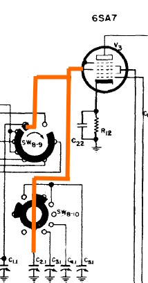
The connection from the grid of V3 to the two wafer switches SW8-9 and SW8-10 is anything but obvious.
See schematic with orange line.
SW8-10 is the side of the wafer that faces the module chassis (front of radio). SW8-9 is the other side. That's one sneaky.
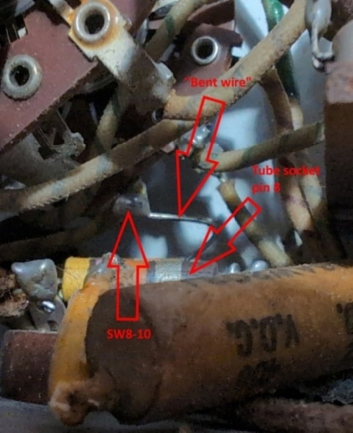
In the "bent wire" photo, note the connection to SW8-10. It's not clear in this photo but the terminal
is on the far side of the wafer. There is a striped wire that goes to one of the big variable tuning
capacitors and a "bent wire" to pin 8 (grid) of the tube.
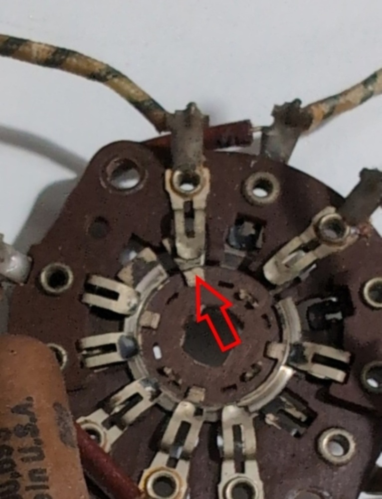
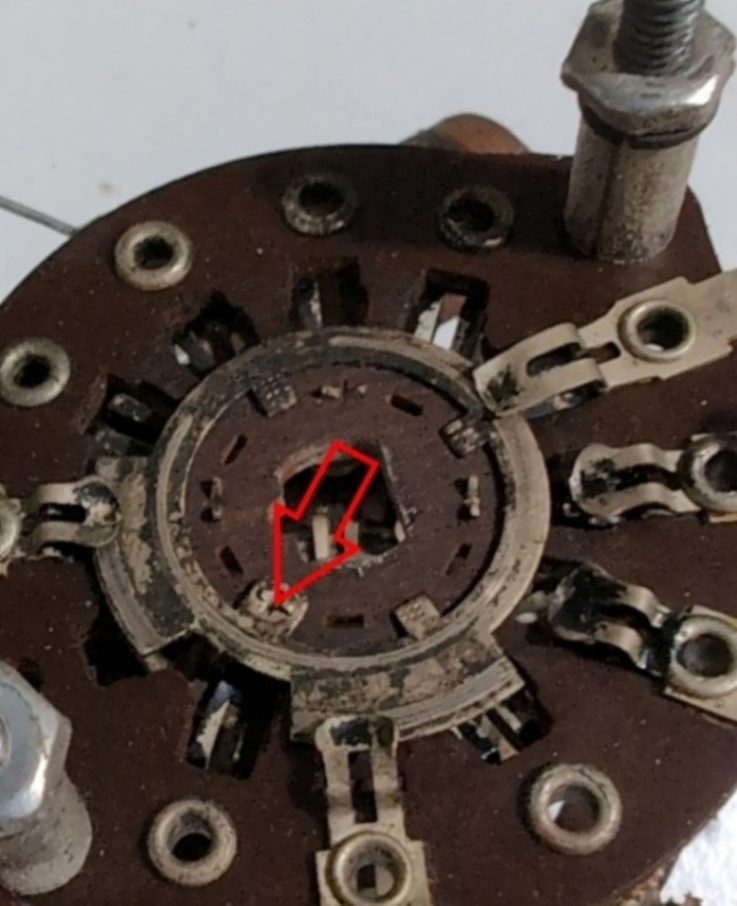
In the SW8-10 photo, note the square bit (arrow) that goes through the rotor. In the SW8-9 photo, note
the other side of the square bit (arrow) that goes to a single width connection tab. That's a serious sneaky.
The "bent wire" is the only connection between the tube socket and the switch assembly. It's my guess that during initial manufacture, they wired the assembled wafers and positioned it near the socket, added the one little piece of wire and bent it as the assembly was moved to and mounted on the chassis above the socket.
Page: /Band_switch/Late/Mix_switch_wafers/Sneaky_bastards/Sneaky.shtml
Last modified: Saturday, 2 May 2026