Copied from War Department manual TM 11-874 (22 November 1944) and editied for style.
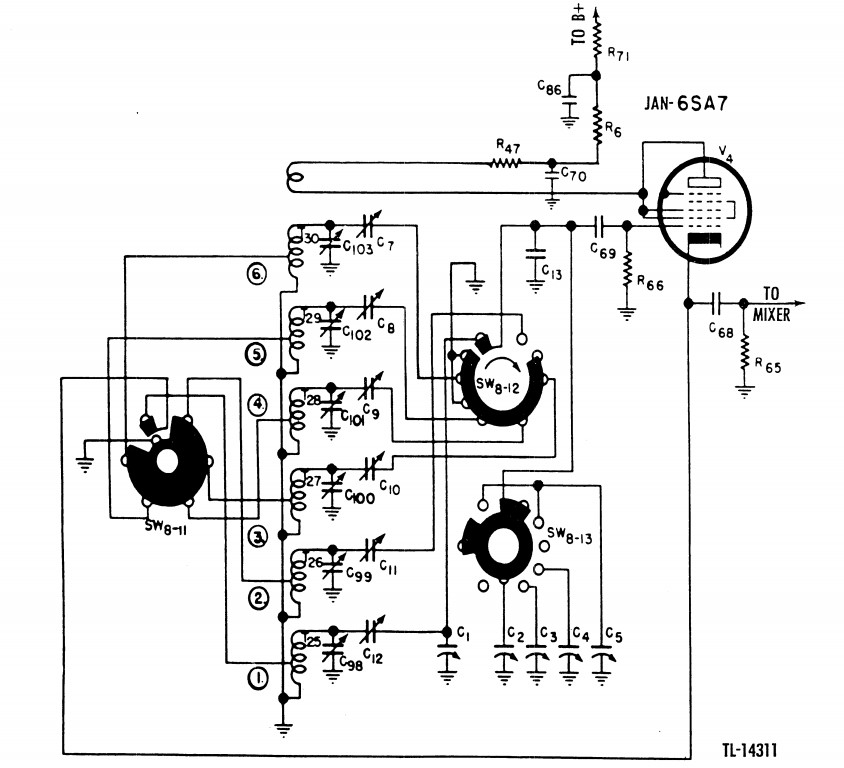
A separate tube 6SA7 (V4) is used as the high-frequency oscillator and produces a frequency 455 KHz above the received signal.
The HF oscillator signal is coupled to the No. 1 grid of the mixer 6SA7 (V3) through capacitor C68 and across resistor R65. Switches SW8-11 and SW8-12 select the proper oscillator coil for the band being used.
Switch SW8-13 shunts the proper ganged tuning capacitor C2, C3, C4, or C5 across the main tuning capacitor Cl.
Trimmers C98, C99, C100, C101, C102, and C103 across their respective coils are adjusted during the alignment procedure.
Low-frequency padders C7, C8, C9, C10, C11, and C12 are adjusted at the factory and need no further adjustment.
The grids, numbers 2, 3, and 4, are connected to the plate and all operate at the plate potential.
This potential is supplied through dropping resistor R71, decoupling resistor R6, and parasitic suppressor R47.
RF voltages are bypassed to ground by capacitors C70 and C86.
Capacitor C13 is a temperature compensating capacitor providing oscillator stability.
Bias is developed across grid leak resistor R66 charging blocking capacitor C69 negative on the grid side.
A misshapen sine wave in a vacuum tube Hartley oscillator is typically caused by overdriving the tube or excessive feedback, which leads to non-linear operation and harmonic distortion.
Excessive Feedback Ratio: If the inductive ratio (tap point) between the two coils is too stiff (e.g., 1:1), the oscillator receives too much feedback, overdriving the grid and causing the output to clip or become erratic.
Solution: Adjust the coil tap to change the feedback ratio (e.g., to 5:1 or similar) to reduce the feedback level to just above the threshold required for oscillation.
Grid Current and Non-Linearity: If the grid voltage swings too positive, grid current flows, causing the Vbe (or grid-cathode voltage) to turn off for more than 50% of the cycle. This introduces sharp current pulses and glitches into the output.
Solution: Increase the input impedance or add emitter degeneration (a small resistor in the cathode circuit for tubes, or emitter resistor for transistors) to stabilize the bias and reduce current swing.
Harmonic Content: Basic LC tank circuits naturally produce outputs rich in harmonic content, which the tank's Q factor filters but may not eliminate entirely if the driving signal is too harsh.
Solution: Ensure the tank circuit operates at a high Q (perhaps half of the unloaded Q) to smooth the non-sinusoidal amplifier currents into a cleaner sine wave.
Lack of Automatic Gain Control (AGC): Without a mechanism to limit amplitude, the oscillator grows until the tube clips against the supply rails.
Solution: Implement an automatic gain limiting circuit (AGC) or rely on the natural clipping of the tube's grid-cathode diode (if designed for Class C or B) to stabilize amplitude, though this may introduce distortion if not filtered properly.
Biasing Issues: Incorrect biasing resistors can load the tank circuit or set the operating point incorrectly, leading to instability or excessive distortion.
Solution: Verify bias resistors are high enough not to load the coils and set the tube in the appropriate class of operation (e.g., Class A for linearity, Class C for efficiency). For vacuum tube specific designs, ensure the grid is not driven beyond the linear region of the tube’s characteristic curve. If the grid becomes positive, it draws current, distorting the sine wave. Using a buffer stage with high input impedance after the oscillator can also help isolate the tank circuit from load variations that might affect waveform purity.
Page: /Alignment/Osc/Theory/Align_early_osc_theory.shtml
Last modified: Saturday, 20 Jun 2026