The BFO is turned on with the switch below the band spread control and adjusted by the skirted knob directly betow the tone control.
The BFO circuit, as will be seen by referring to the schematic, is the weil known Hartley oscillator. It will be noticed char a plate dropping resistor is used to compensate for plate volcage vartations.
An increase tn receiver voltage causes an Increase in the plate current of the oscillator. This increase in turn causes the volcage drop across the resiscor to increase, thus maintaining a more constant voltage at the place of the beat oscillator cube.
A favorable ratio of capacity to inductance is used. The fixed tank capacity has been artifically aged by alternately exposing it to very high and then low temperatures. In this manner any residual strains of the component parts are removed and che capacicy of the condenser remains constant.
The BFO coil is permeability tuned which further removes the possibility of drift which would occur should uw compression variable be used ta resonate the circuit.
Proper location of the Beat Oscillator tube and its assuciated camponents plus excellent shielding and mechanical rigidity do much to keep stray fields from being established.
Little BFO leakage is to be expected in the Model SX-28 so “tweets” or BFO harmonics will not prove to be bothersome.
I can just imagine the conversation at some staff meeting about the above text...
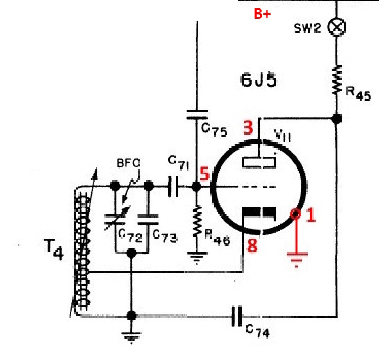
The BFO uses a 6J5 (V11) in a Hartley circuit, with feedback taking place between the cathode and grid sections of inductor T4. Fixed capacitor C73, shunted by variable capacitor C72, and the permeability tuned inductor T4, constitute a tuned circuit resonant to the intermediate frequency.
The variable capacitor C72 is adjusted by means of the B.F.O. control on the front panel to vary the frequency of the BFO and consequently the frequency of the resultant beat note. Switch SW2 controls the operation of the BFO by supplying or interrupting the plate potential applied to the tube through dropping resistor h45. Capacitor C74 serves as a plate bypass. Bias for the tube is supplied by grid current passing through resistor R46, C71 acting as a blocking capacitor. The output of the oscillator is taken from the grid circuit of tube V11 and applied to the diode detector through capacitor C75.
Page: /Alignment/BFO/Align_early_bfo_theory.shtml
Last modified: Sunday, 21 Jun 2026